
PROFIBUS Manual
Two formats exist for entries in the GSD file. In an initial version, user-specific parameters are defined with a parameter pair and, in an extended version (GSD revision 1 at least) the individual parameter values can be provided with texts and also assigned to individual modules.
These two versions should not occur simultaneously in a single GSD file. If both versions are indicated, the version listed last in the GSD applies.
Simple version
User_Prm_Data_Len = 5
User_Prm_Data = 0x00, 0x10, 0x00 , 0x00, 0x2F
In this example the user-specific parameters are defined for a fixed length of 5 bytes. With the second key word, the values of individual bytes are defined. In the Set_Parameter telegram therefore, 7 standardized and then these 5 user-specific bytes will be transmitted, i.e. 12 bytes in total.
Extended version (from GSD revision 1)
In an initial block, texts are assigned to individual parameters and their values:
PrmText= 1
Text (0)= "disable"“ ; Value 0 means disable
Text (1)= "enable" ; Value 1 means enable
EndPrmText
In the second block, individual parameters are described. Default values and possible value ranges are defined. In this example, the text from description 1 is assigned to bit 5.
ExtUserPrmData=1 "Diagnostic Alarm"
Bit (5) 1 0-1
; Bit 5 has preallocation 1 and value 0 or 1
Prm_Text_Ref = 1
; Bit 5 in this reference relates to PrmText=1
EndExtUserprmdata
The maximum length of user-specific parameters is now indicated. Less can also be specified. The specification of this parameter excludes the specifications of parameter User_Prm_Data!
Max_User_Prm_Data_Len = 50
Parameters can now be defined for the device. In the first key word, parameters can be preallocated with values. From a specific byte (here 0, i.e. the 8th byte in the Set_Parameter telegram) 4 bytes are preallocated values in this example. When using this key word, User_Prm_Data can no longer apply.
Ext_User_Prm_Data_Const (0) = 0x00,0x01,0x02,0x03
Possible settings can now be listed for the individual bytes. This is done by indicating which parameters can be used in which byte. In this example, the second user-specific byte (the 10th byte in the Set_Parameter telegram) will be set with parameter description 1:
Ext_User_Prm_Text_Ref(2) = 1
The texts referenced must be located before the reference itself.
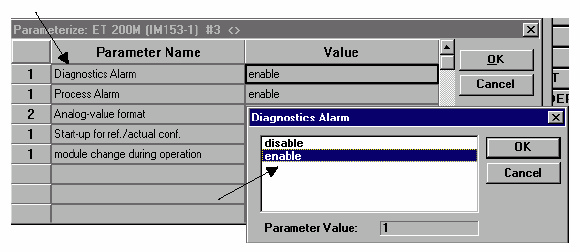
During project development, the user wants to determine whether a diagnostic alarm (which depends on byte 2 of the user parameters (Ext_User_Prm_Const (0) ) should be generated or not. The preallocation is that no diagnostic alarm should be generated. If the user wants to change this behaviour, he can select the reaction symbolically according to the previous reference (Ext_User_Prm_Text_Ref(2)=1 to ExtUserPrmData=1 "Diagnostic Alarm" to PrmText= 1 ).
In the project development tool (here COM PROFIBUS from Siemens) the planned project texts in the GSD file are displayed while the user parameters are being planned:
Parameters for an individual module can also be defined in the same way. The additional key word Ext_Module_Prm_Data is used for this purpose.
Module "Demo-Module" 0x00
Ext_Module_Prm_Data_Len = 2
; this module has two parameter bytes
Ext_User_Prm_Data_Const (0) = 0x00, 0x00
; both bytes are preallocated
Ext_User_Prm_Data_Ref(0) = 1
; byte 0 is set according to description 1
EndModule
The sum of all user parameters must not exceed Max_User_Prm_Data_Len!
