PROFIBUS Manual
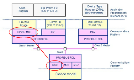
With PROFIBUS there is differentiation between class 1 or 2 masters and slave devices. These devices communicate using different communications relationships.

Model of the PROFIBUS communication
Here we consider the case of a controller communicating with its remote peripherals, i.e. the slave devices. The abbreviation DP stands for decentralized periphery. In our example, we designate the controller as a class 1 DP master and the peripheral input and output elements as DP slaves. This communications protocol is called MS0. The MS1 and MS2 communications relationships are used for the acyclic control of parameters and are explained in a later chapter.
The class 1 DP master (controller) will poll individual DP slaves (peripherals). It always writes all the output values of a DP slave and receives from it in return an immediate response with all input values. The DP master does this in the same way with all DP slaves, one after the other. After a cycle, it starts again from the beginning. In this way the controller forms a process image with data from the remote periphery.
The DP master must be configured before it can start its communication. It must know which DP slaves it has to control on the PROFIBUS and which data are to be exchanged. It needs the description of the communications characteristics of connected devices. With PROFIBUS, this is supplied in electronic format as the general station description in the GSD file. By reading in this GSD file, a configuration tool can become familiar with the communications characteristics of a DP slave, it becomes an electronic datasheet.
In the following chapters the basic functions of PROFIBUS-DP are explained. Every chapter also clarifies the descriptions in the GSD and the relevant telegrams.
