PROFIBUS Manual
In isochronous operation, slave application cycles and, to a limited extent, also master application cycles are synchronized with the equidistant bus cycle on the PROFIBUS.

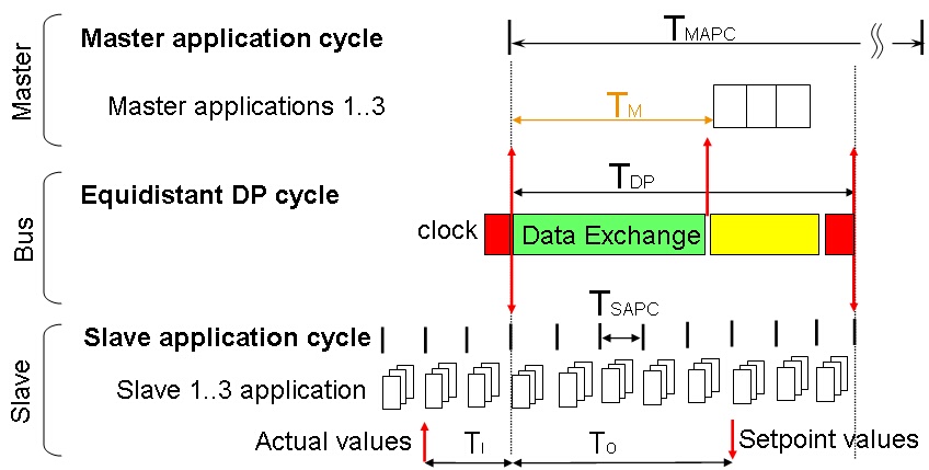
Structure of an isochronous bus cycle
The equidistant DP cycle TDP determines the cycle of all bus users.
The DP master has a master application cycle TMAPC that generally lasts longer than the DP cycle. The communications module informs the application when cyclic data ends (TM) so that calculation of control algorithms may commence without delay.
The DP slave has a local slave application cycle TASPC, which is a multiple integer of the DP cycle. This local slave application cycle is used like a local clock and is synchronized as a phase locked loop (PLL) with PROFIBUS clock telegrams (global control with group 8). Actual position values (input data TI) are captured for a defined number of local cycles before the PROFIBUS cycle. Setpoint values (output data TO) are transferred later to a defined number of local cycles. In the simplest case, both times TI and TO are zero.
The following parameters are therefore necessary for an isochronous bus cycle:
Parameter |
Unit |
Permitted values |
|---|---|---|
TBASE_DP |
Time base for TDP (in units of 1/12µs) |
375, 750, 1500, 3000, 6000, 12000 |
TDP |
DP cycle (in units of TBASE_DP) |
1 to 216-1 (min 500µs, max 32 ms) |
TMAPC |
Master application cycle (in units of TDP) |
1 to 14 |
TBASE_IO |
Time base (in units of 1/12µs) for times TI and TO |
375, 750, 1500, 3000, 6000, 12000 |
TI |
Time TI (in units of TBASE_IO) |
0 (special case), 1 to 216-1 |
TO |
Time TO (in units of TBASE_IO) |
0 (special case), 1 to 216-1 |
TDX |
Time TDX (in units of 1/12ms) |
0 (special case), 1 to 232-1 |
The necessary settings are transferred in the parameter telegram as a data block to the DP slave.
A DP slave's capabilities for the isochronous cycle are described in the GSD file. These key words were only defined with revision 4 of GSD syntax.
Isochron_Mode_supp = 1
This DP slave supports the isochronous bus cycle. If 0 (=FALSE) appears here, all other parameters are invalid.
Isochron_Mode_required = 0
If this value is 1 (=TRUE), the DP slave can only work with an isochronous bus cycle. This can be the case with drive position control, for example.
TBASE_DP = 1500 ; 1500 * 1/12 µs = 125 µs
TDP_MAX = 256 ; 256 * 125µs = 32ms
TDP_MIN = 16 ; 16 * 125µs = 2ms
TDP_MAX must not exceed 32 ms. On the basis of these values, a planning tool will plan the DP cycle as an integer multiple of individual parameters.
T_PLL_W_MAX = 12 ; equal 12*1/12 μs = 1μs
The maximum value of acceptable jitter for this field device based on 1/12 μs.
TBASE_IO = 1500 ; 1500 * 1/12 μs = 125μs
TI_MIN = 1 ; 1 * 125μs = 125μs
TO_MIN = 1 ; 1 * 125μs = 125μs
The value TI_MIN = TO_MIN = 0 forces the master to set parameters TO and TI to zero (simplified operation).
